|
|
|
Categories
|
|
Information
|
|
Featured Product
|
|
|
 |
|
|
There are currently no product reviews.
 ;
I was so happy that the owner's manual was available. It is well written and helped me to use the radio/CD player/recorder without problems. Thanks for making it available.
Irene Lambert
;
Excellant!!! Very quick and easy....Best $4.99 I have spent in a very long time..
I highly recommend this.
;
Thanks so much for the Owner's manual for my Sony PS - FL1. I had purchased the turntable off of eBay. It came in and looked great. Packed well and appeared to be great. I balanced and aligned the tone are and hooked it up. When trying to play a record the tone are would move to the right place and just before it would drop to play it moved back off the edge of the record before touching down. I searched the net for an answer to this issue. No luck. Then I purchased the owners manual and sure enough there was a place to adjust where the stylus touched down. That adjustment solved the problem and saved me a $35 feet to have the player checked out. The manual is well written and easy to understand. It is a must have for anyone with this front loading Sony turntable.
;
Some years back I pruchased a Sansui G-9000. I had it cleaned up and a problem with the left channel repaired. When I got it back I hooked it up to my tape decks, turn tables, TV and it played great. The only thing I was not really satisfied with was the performance of my Graphic Equalizer. I purchased this owner's manual had poured myself a cup of coffee. The manual is well organized and written in plain language. It also contained the solution to my dissatisfaction. By using the preamp connections coupled I was able to run everything through my graphic equalizer and now enjoy the full potential of my complete system.
 ;
An excellent service for the price, however, it would also have been handy if the troubleshooter pages were included. The manual is only sent in the language of your country, thus it looks as though there are some pages missing. Otherwise highly recommended.
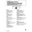
Connecting
Mounting
1. Attach the fall prevention wire to the
camera, followed by attaching it to the ceiling slab (Fall prevention wire is not included.) Connect the video signal cable. (A pg. 14) Lower the cover and connect the connectors. Upon connecting, cover the connectors using the protection cover. (A pg. 15) Install the Ferrite core (TK-C210FW only) (A pg. 14) Connect the alarm cable. (TK-C215V12 only) (A pg. 15) Wrap insulation tape around cables. Insert the camera unit into the ceiling hole.
1. Align j with the shooting direction when
mounting the camera.
2.
2. Fasten the camera. (x3 locations)
A Press the screw head of the clamping bracket
all the way in using a cross screwdriver.
B With the screw pressed in using the
screwdriver, turn about 90 in the clockwise direction, followed by pulling out the screwdriver.
3. Connect the input power supply cable. 4. 5. 6. 7.
C The clamping bracket is attached to the ceiling
and the camera fastened.
NOTE:
Dismantle the camera upon turning the screw heads of the ceiling mount bracket (x3) by 90 in the anti-clockwise direction.
7.
Fall prevention wire (not supplied) Protection cover
Alarm signal cable (TK-C215V12 only)
3.5. or crimp Solder
2.
Insulation tape
1.
6.
Wrap with tape
1.
F U RO P NT
Input power supply cable
B A
Align with shooting direction
2.
*TK-C215V4 is used in the above illustration
Adjusting Images
*TK-C215V12 is used in the above illustration
After mounting is completed, adjust the images while checking the actual image. (A pg. 23 AAdjusting ImagesB)
19
|
|
|
> |
|