|
There are currently no product reviews.
 ;
I would not plug this machine in without finding a manual like this. In addition to setup and normal operating instructions, it has troubleshooting flowcharts, diagrammed mechanical adjustments, and schematics to beat the band. The tech I hand it to would be thrilled to find solder side PCB diagrams with component outlines superimposed, pinouts for every IC chip, and line drawings of transistors, with labeled legs.
As for printing quality, this may be a copy of a copy, but even the finest print when enlarged is very legible. There is a bit of grayed print over a few pages, as if a wet page were placed over it, but the print is still very legible. If you could borrow an original manual and get it printed and bound for 4 to 6 times the cost, you could get better quality. In that case you wouldn't be here. For price, utility, and availability I am rating this manual highly.
;
I received the Manual in a timely manner and it was exactly what I needed.
This is a perfect copy of the Service Manual, The quality is great. I am very
happy. Thank you
;
exactly as they say. Within 24 hours the link to the pages and offcourse it was the right service manual. Super and thanks
 ;
The manual was exact the thing that was promised. My old car stereo is working again thanks to the information supplied.
;
I PURHASED THIS PRODUCT BECAUSE I WAS HAVING PROBLEMS WITH MY CDR20 HARMAN KARDON RECORDER. WHICH I PURCHASED NEW 12 YEARS AGO. AFTER REVIEWING THE MANUAL, I WAS ABLE TO ADJUST THE TENSIONER IN THE SYSTEM. WORKS LIKE A CHAMP!.
SAVED ME AT LEAST 100.00 WHICH WAS WHAT A SERVICE REPAIR STATION WANTED. GREAT MANUAL EASY TO READ. SPECIALLY AFTER I PRINTED THE PAGES WHICH DEALT WITH MY RECORDER. THANKS A LOT!!!!!!!!
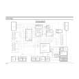
Alignment and Adjustment
5-3 Head Switching Point Adjustment
1) Playback the alignment tape. 2) Press the �SW703� button on Main PCB with pincers to set the adjustment mode. (See Fig. 5-2 ) 3) Press the �SP/LP� button of remote control then adjustment is operated automatically. (See Fig. 5-1) 4) Turn the Power off.
5-4 NVRAM Option Setting
1) NVRAM Option is adjusted at production line basically. 2) In case Micom (IC601) and NVRAM (IC605 ; EEPROM) is replaced, be sure to set the corresponding ooption number of the repaired model. (If the option is not set, the unit is not operated.) 1) Press the �SW703� button on Main PCB to set the adjustment mode. (See Fig. 5-2) 2) Press the �MENU� button on the remote control about 5 seconds then option setting display is appeared. (See Fig. 5-14) 3) Select the option number (See Table 5-2) of corresponding model with �CURSOR� button on the remote control. 4) If selecting the option number is completed, press the �OK� button of remote control. (If �OK� button is pressed, the selected number is changes reversed color. ; See Fig. 5-14) 5) Press the �MENU� button of remote control again to store the option number. (�PLEASE WAIT� is displayed for a second as shown Fig. 5-15 and this setting is completed.) 6) Turn the Power off.
01 09 17 25 33 41 49 57 65
02 10 18 26 34 42 50 58 66
03 04 05 06 07 08 11 12 13 14 15 16 19 20 21 22 23 24 27 28 29 30 31 32 35 36 37 38 39 40 43 44 45 46 47 48 51 52 53 54 55 56 59 60 61 62 63 64 67 68 69 70 71 72 CNG : OK SAVE : MENU
Fig. 5-14 <Table 5-2>
01 09 17 25 33 41 49 57 65
02 10 18 26 34 42 50 58 66
03 04 05 06 11 12 13 14 19 20 21 22 27 28 29 30 35 36 37 38 43 44 45 46 51 52 53 54 59 60 61 62 67 68 69 70 PLEASE WAIT
Fig. 5-15
07 15 23 31 39 47 55 63 71
08 16 24 32 40 48 56 64 72
MODEL V-631UK
OPTION NUMBER 4, 5, 6, 8, 9, 10, 11, 14, 18, 25, 26, 29, 30, 33, 38, 40, 41, 46, 49, 50, 53, 60, 61, 64
5-8
Toshiba
|