|
|
|
Categories
|
|
Information
|
|
Featured Product
|
|
|
 |
|
|
There are currently no product reviews.
 ;
A good manual. Had everything i needed to make the repair.
;
This manual is a complete guide, including later additions. It has all the necessary information about the replacement items. The material quality is great to read.
 ;
This manual is very helpful, correct shematic diagram, and good exploded view.Perfect!
;
Alte gescannte Servicepläne sind oft doch etwas undeutlich . Stromlaufpläne werden auf mehrere DIN A4 Seiten aufgeteilt. Alles ziemlich umständlich und zeitaufwendig. Aber mit etwas Mühe geht alles.
;
Great item, high resolution, detailed, very easy to work with.
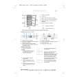
VC-SA66W VC-SH77 VC-SH97
ADJUSTMENT OF TAPE DRIVE TRAIN
1. Tape run rough adjustment 1 Remove the cassette housing control assembly. 2 After shortcircuiting TP801 provided at the center (facing to the main PWB), plug in the power cord. 3 Check and adjust the position of the tension pole. (See page 17.) 4 Check and adjust the video search rewind back tension. (See page 17.) 5 Connect the oscilloscope to the test point for PB CHROMA envelope output (TP201). Set the synchronism of the oscilloscope to EXT. The PB CHROMA signal is to be triggered by the head switching pulse (TP202). 6 Set the alignment tape (VROCPSV) to play. (Put a 500g weight on the cassette tape to prevent lift of cassette tape.)
Guide roller Cassette Tape
Notes: 1. Previously set the tracking control in the center position, and adjust the envelop waveform to maximum with X value adjustment nut. Thereby the tape run rough adjustment is facilitated. 2. Especially the outlet side envelope waveform must have higher flatness.
Figure 4-32. 2. Adjustment of A/C head height and azimuth 1 Perform the initial setting of A/C head position by the method stated in "Page 20 Replacement 3". 2 Connect the oscilloscope to the audio output terminal. 3 Using the alignment tape in which 1 kHz linear audio signal has been recorded, adjust the height screw so as to get max audio output. 4 Using the alignment tape in which 6 kHz linear audio signal has been recorded, adjust the azimuth screw so as to get max audio output. 5 Repeat the above adjustment steps 3 and 4 a couple of times. Finally take the step 4 again.
500g
Weight of 500g
Figure 4-31. 7 Press the tracking button (+), (�) and change the envelope waveform from max to min and from min to max. At this time make sure that the envelope waveform changes nearly parallel. 8 Unless the envelope waveform changes nearly parallel, adjust the height of supply side and take-up side guide roller so that the envelope waveform changes nearly parallel. (For envelop adjustment procedure refer to Figure 4-35.) 9 Turn the tilt screw to remove the tape crease at the fixing guide flange. Play back the tape and check for tape crease at the fixing guide flange. (1) If there is no tape crease Turn the tilt screw clockwise so that tape crease appears once at the flange, and then return the tilt screw so that the crease disappears. (2) If there is tape crease Turn counterclockwise the tilt screw so that the tape crease disappears. (Reference) If the tilt screw is turned clockwise crease appears at the lower flange.
For X value adjustment Adjust the X value, turning the geartype screwdriver.
Figure 4-33.
22
|
|
|
> |
|