|
|
|
Categories
|
|
Information
|
|
Featured Product
|
|
|
 |
|
|
There are currently no product reviews.
 ;
I found this service manual to be complete in every detail except for troubleshooting charts. It would be helpful if it had a set of troubleshooting charts; however it is a very good manual otherwise and for the price it is very well worth it.
 ;
Complete manual included schematics layouts and alignment procedure, clear to read and magnify, extremely pleased with manual and owner manual . com's service
;
perfect, i am very satisfait for the réception of the sansui r-5l service manual, thank you very much
;
Thank you, this is a rare document. Few others have it, but they charge way more for a download.
Great deal (even if you have to wait a few hours to get it).
;
The purchased manual is an high quality scan of the original Philips paper-based Service Manual. I am very satisfied!
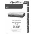
5. A/C HEAD HORIZONTAL POSITION ADJUSTMENT
Purpose: To adjust the Horizontal Position of the A/C Head. Symptom of Misadjustment: If the Horizontal Position of the A/C Head is not properly adjusted, a maximum envelope cannot be obtained at the Neutral Position of the Tracking Control Circuit. Place a jumper between TP6003 on the Video Signal Process Section and +5V(TP6009) on the System Control Section of the Main C.B.A. to defeat Auto Tracking. 1. Eject the tape and insert it again to access the Neutral Tracking position. Connect the oscilloscope to TP3002 on the Video Signal Process Section of the Main C.B.A. Use TP6205 as a trigger. 2. Play back the alignment tape and confirm that the RF envelope appears. 3. If adjustment is required, loosen the Black Screw (D) and tighten it lightly. Set the H-Position Adjustment Driver into the Hole (A). Then slowly turn the fixture either clockwise or counterclockwise so that the envelope is at maximum. 4. Before finding the center of the maximum period of the envelope, rotate the fixture back and forth slightly to confirm the limits on either side of the maximum period. 5. Push the Tracking Control Up Button (on the Remote Control) several times (count the number of times pushed) until the maximum envelope is reduced to 1/2. 6. Reset the tracking to the neutral position by ejecting the tape and reinserting it. Push the Tracking Control Down Button (on the Remote Control) several times (count the number of times pushed) until the maximum envelope is reduced to 1/2. 7. If the number of pushing is not the same, then loosen the Black Screw (D) and set the H-Position Adjustment Driver into the Hole (A) to find the center point. Then repeat the above procedure to determine the center point. 8. Tighten Black Screw (D). 9. Remove the jumper between TP6003 and +5V(TP6009).
Black Screw (D)
Hole (A)
Fig. M11 Note: Old type of H-Position Adjustment Driver (VFK0136) can be used for this adjustment.
2-23
|
|
|
> |
|
|
Parse Time: 0.24 - Number of Queries: 99 - Query Time: 0.059