|
|
|
Categories
|
|
Information
|
|
Featured Product
|
|
|
 |
|
|
There are currently no product reviews.
 ;
Very complete and well reading drawings. Documentation is essential for successful repairs.Good documentation, with all that is necessary. This manual was what I was waiting with all the information necessary for the repairing I need it for. You must buy it if you want to do repairs or simply understand how it works.
 ;
Excellent service manual includes everything is need to repair this radio-caseete, how to disassemble, wiring diagram, all , waiting time until the download was only a few hours. I'm going to buy service manuals from here, are cheap and very good.Thank you.
;
Good service manual,i saved from scrapping this deck,is now fully functional.Thanks.
;
Found this to be the manual included with the original packinging, was helpfull but did not give any detailed repair instructions.
;
Complete service manual, was very helpful in repairing this tapedeck.Thanks.
3-7-2. Video Memory SIZE/SHIFT/BLKG Adjustments
1. Input the monoscope signal to VIDEO IN. 2. Press the INPUT SELECT VIDEO key to project the monoscope signal on the screen. 3. Select VIDEO MEMORY 1 using the SWITCHER/ VIDEO MEMORY/INDEX changing switch and the SWITCHER/VIDEO MEMORY/INDEX key. 4. Press the RGB SHIFT key and adjust the center of the monoscope signal to the screen center using the �, �, � and � keys. 5. Press the RGB SIZE key and adjust the horizontal and vertical sizes of the monoscope signal to 4:3 using the �, �, � and � keys. 6. Press the BLKG key to adjust the screen top blanking to the position 40 ± 10 mm outside the effective screen using � and � keys. 7. Press the MEMORY key. 8. Store the data of VIDEO MEMORY 1 to VIDEO MEMORY 2 to 5, too. 9. Select VIDEO MEMORY 6. 10. Press the RGB SHIFT key and adjust the center of the monoscope signal to the screen center using the �, �, � and � keys. 11. Press the RGB SIZE key and adjust the horizontal and vertical sizes of the monoscope signal to 4:3 using the �, �, � and � keys. 12. Press the BLKG key to adjust the screen top blanking to the position 40 ± 10 mm outside the effective screen using � and � keys. 13. Store the data of VIDEO MEMORY 6 to VIDEO MEMORY 7_10, too.
3-8. HIGH VOLTAGE SCREEN DISTORTION ADJUSTMENT
1. Select INPUT A and input the fH = 64 kHz RGB stripe signal to the RGB terminals. 2. Press CONTR (+) and BRIGHT (+) to set the contrast and bright levels to the maximum. 3. Adjust RV1 of the EA board so that the left and right vertical lines of the stripes can be straight.
NG
OK
3-9. PROCEDURE AFTER COMPLETING ADJUSTMENTS
After completing all adjustment, change the dip switch S201-1 on the YA board from �OFF (right)� to �ON (left)� to save the adjustment data in the memory.
VPH-G90E/G90U/G90M
3-19
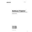 $4.99 VPHG90E SONY
Owner's Manual Complete owner's manual in digital format. The manual will be available for download as PDF file aft…
|
|
|
> |
|