|
|
|
Categories
|
|
Information
|
|
Featured Product
|
|
|
 |
|
|
There are currently no product reviews.
 ;
Very good manual. Plenty of service information including alignment instructions. Clear circuit diagram. Excellent, thank you.
 ;
Good morning, the service manual you sent me was perfect.
Your service and answering are excellent.
I recomend this service.
Best regards.
;
I had been looking everywhere for a proper service manual for this VCR. Everywhere else that has this available for download has a very light version. This is the full service manual with all aspects that would interest anyone looking for the service manual for the AIWA HV-MX100 Worldwide VHS VCR. Great quality (as always). A winner hands down. Best Quality.
;
Top quality manual. Covers all aspects you'd expect in a top quality service manual for this Panasonic VHS VCR. The manual resolution is high. Another top quality manual from the only site worth downloading manuals from! If you're looking for a manual for the PV-9662 VHS VCR, this is the one you'll want to get!
;
complete part-lists and pcb layout, schematic diagram is good enlargable,
1
2
3
4
C
A
R452 C414 SY IN
VCSDA
b-2
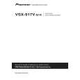
Is there a Y signal? Yes C420 SC IN No Diagnose between the BOARD TO BOARD Assy and S. VIDEO Assy.
d-1
Is there a same signal as VCSDA (0 to 3.3 V)? Yes R454 VCSCL No Check the Q451. If Q451 is failure, replace Q451.
b-3
B
d-2
Is there a same signal as VCSCL (0 to 3.3 V)? Yes No Check the Q451. If Q451 is failure, replace Q451.
Is there a C signal? Yes
No
Diagnose between the BOARD TO BOARD Assy and S. VIDEO Assy.
Note: Check is unnecessary because component input does not convert it.
Step 3-5: VIDEO CLK, DATA
IC701 (Pin 48) LLC1
Step 3-3: Reset
CN318 (Pin 2) XVCRST
e A
C
Is there a clock (27 MHz)? Yes IC701 (Pins 2 to 9)
No Check the parts and patterns in the path (IC401). If IC401 is failure, replace IC401.
Is the voltage "H" (5 V)?
No Diagnose between the BOARD TO BOARD Assy and MAIN Assy.
P8 to P15
X'tal
Yes
f
IC401 (Pin 22) Is there the CLK (28.63636MHz) ? Yes
D
XTAL
c
No Check the X401 or IC402. If X401 or IC402 is failure, replace X401 or IC402.
Is there a data?
No Check the parts and patterns in the path. If IC401 is failure, replace IC401.
Yes
Step 3-6: Video Output
IC701 (Pin 35) DACA
Step 3-4: I2C
CN318 (Pin 4) Does a signal output in constant period (0 to 5 V) ? Yes
E
g-1
VCSDA Is there a composite signal? Yes CN316 (Pin 21) No Check the parts and patterns in the path. If IC701 or R731 or R732 or Q731 is failure, replace it. CVBS OUT
A
No Diagnose between the BOARD TO BOARD Assy and MAIN Assy.
a
VCSCL Is there a composite signal? Yes IC701 (Pin 33) DACB No Check the parts and patterns in the path. If Q731 or R733 is failure, replace Q731 or R733. No Diagnose between the BOARD TO BOARD Assy and MAIN Assy.
CN318 (Pin 3)
A
Does a clock output in constant period (0 to 5 V) ? Yes
g-2
Is there a Y signal? Yes No Check the parts and patterns in the path. If IC701 or R741 or R742 or Q741 is failure, replace it.
F
D
112
1 2
VSX-917V-K
3 4
|
|
|
> |
|