|
|
|
Who's Online
There currently are 6043 guests online. |
|
Categories
|
|
Information
|
|
Featured Product
|
|
|
 |
|
|
There are currently no product reviews.
 ;
I recently purchased a manual for a Samsung DLP tv to help with a trouble shooting problem I was having. Every tv repair shop wanted close to $400.00 for the fix, but after I found Owner-Manuals.com I hit pay dirt. The manual they had for me to purchase and download was a complete service manual for the exact tv I needed. It was complete with wiring diagrams, schematics, and even part numbers. If your the fix it yourself type I highly recommend trying to find any manual here before paying someone else to fix whatever problem your having.
;
Once again, excellent price and manual delivered in a timely manner and as advertised!
;
Outstanding quality manual. This is the exact documentation I needed to service my AKAI GX-210D. This is a PERFECT COPY of the service manual for my machine. Outstanding service. Thank-you!
;
This service manual have great value... Recommended A+++++++
;
This service manual have great value... Recommended A+++++++
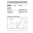
ELECTRICAL ADJUSTMENTS
2-5: STEREO SEPARATION NOTE: Adjust after performing adjustments in section 2-4. 1. Receive the stereo signal. (L=2KHz, R=400Hz) 2. Connect the AC voltmeter to AUDIO OUT L/R through stereo filter (L=400Hz, R=2KHz). 3. Check if the difference between with the stereo filter and without the stereo filter is more than 23dB. 2-9: HORIZONTAL SIZE NOTE: Adjust after performing adjustments in section 2-8. Measurement Equipment Maker: SHIBASOKU Co. Limited Measurement Equipment Model No.: DIGITAL TEST PATTERN GENERATOR 588 1. Receive the monoscope pattern. 2. Adjust the VR401 until the SHIFT quantity of the OVER SCAN on right and left becomes 10 ± 2%. (Simple Adjustments) 1. Activate the adjustment mode display of Fig. 1-1 and press the channel button (6) on the remote control. The Fig. 2-5 appears on the display. 2. Press the channel button (6) on the remote control. 3. Adjust the VR401 until the right vertical line of the pattern becomes fit to the right end. 1. EXTERNAL 2. BLACK 3. WHITE (100) 4. WHITE (60) 5. CROSS (100) 6. CROSS (60) 7. 8.
(TV SECTION)
2-6: CONSTANT VOLTAGE 1. Connect the digital voltmeter to TP501. 2. Set condition is AV MODE without signal. 3. Adjust the VR502 until the DC voltage is 111 ± 0.5V. 2-7: OSD HORIZONTAL 1. Using the remote control, set the brightness and contrast to normal position. 2. Activate the adjustment mode display of Fig. 1-1 and press the channel button (5) on the remote control. The Fig. 2-2 appears on the display. 3. Press the channel button (4) on the remote control. 4. Press the VOL. UP/DOWN button on the remote control until the difference of A and B becomes minimum. (Refer to Fig. 2-3) [ TV ]
0. RETURN
"The adjustment items 1, 2, 3, 4 and 5 are not used for this model." Fig. 2-5 2-10: VERTICAL SIZE NOTE: Adjust after performing adjustments in section 2-9.
OSD H
1. Receive the cross hatch signal from the Pattern Generator. 2. Using the remote control, set the brightness and contrast to normal position. 3. Activate the adjustment mode display of Fig. 1-1 and press the channel button (1) on the remote control. The Fig. 2-4 appears on the display. 4. Press the channel button (3) on the remote control. 5. Press the VOL. UP/DOWN button on the remote control until the rectangle on the center of the screen becomes square. 6. Receive a broadcast and check if the picture is normal. 2-11: VERTICAL LINEARITY NOTE: Adjust after performing adjustments in section 2-10. 1. Receive the cross hatch signal from the Pattern Generator. 2. Using the remote control, set the brightness and contrast to normal position. 3. Activate the adjustment mode display of Fig. 1-1 and press the channel button (1) on the remote control. The Fig. 2-4 appears on the display. 4. Press the channel button (5) on the remote control. 5. Press the VOL. UP/DOWN button on the remote control until the SHIFT quantity of the OVER SCAN on upside and downside becomes minimum. 0. RETURN
A 2-8: HORIZONTAL PHASE
B
Fig. 2-3
1. Receive the center cross signal from the Pattern Generator. 2. Using the remote control, set the brightness and contrast to normal position. 3. Activate the adjustment mode display of Fig. 1-1 and press the channel button (1) on the remote control. The Fig. 2-4 appears on the display. 4. Press the channel button (1) on the remote control. 5. Press the VOL. UP/DOWN button on the remote control until the right and left screen size of the vertical line becomes the same. 1. H. PHASE 2. H. BLK 3. V. SIZE 4. V. POSI 5. V. LIN 6. V. SC 7. V. COMP 8. (H FREQ)
"The adjustment item 8 is not used for this model." Fig. 2-4
D2-2
 $4.99 VX-F205 AIWA
Owner's Manual Complete owner's manual in digital format. The manual will be available for download as PDF file aft…
|
|
|
> |
|