|
|
|
Categories
|
|
Information
|
|
Featured Product
|
|
|
 |
|
|
There are currently no product reviews.
 ;
This manual was the factory original. Excellent value and contained all the details I needed. Easy dowwnload provided the information when I needed it.
 ;
Impeccable, document très complet. Perfect, i get all i need. All schematic are correct. Thanks
;
The manual is of better quality compared to other. I found it less expensive and therefore it it is the best buy cost vs quality.
;
I bought the service-manual of the sony ICB-1020(an old transmitter-receiver) at "www.Owners-Manual.com", I found the service-manual for a fairly cheap price(in comparison with other sellers). I filled in some questions, payed the order with Ideal, and within 24 hours I had my service manual. I was very happy:In no time I had my service-manual and everything, but literally everything was noted down in the manual; the electronic scheme, the parts list, etcetera.
A very practical, reference-document.
;
This comprehesive service maual was greatly appreciated, as was the digital download.
SECTION 1 SERVICING NOTES
This set detects the rotation of GEAR (PH) using the PH701 (photo reflector). The PH701 is mounted on the MAIN board, and therefore the GEAR cannot be detected with the MAIN board removed. As a result, the motor cannot be controlled, causing malfunction. Further, the S702 (FWD/REV switch) is also mounted on the MAIN board, and with the board removed, the mechanism position cannnot be detected and the operation is not changed over. Therefore, when the voltage check is executed with the MAIN board removed, follow the procedure provided below.
Note : Do not move the S702 swithc position when removing the MAIN board. If it is moved, the set will not be changed over to the selected mode. In this case, reconnect the MAIN board to the set and retry the work from the beginning.
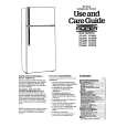
1. Setting 1) Refer to �3. DISASSEMBLY�, and remove the cabinet and open the MAIN board. 2) Connect the MAIN board to the M901 (motor) and PM901 (plunger) using jumper wires. 3) Short the ATS terminals. 4) Press and fixed the S701 (CASSETTE HOLDER). 5) Supply 1.5V to the battery terminals � and � using a stabilized power supply. 2. FF, REW Modes 1) Input a square wave to the TP35 (PHOTO IN) and TP23 (GND). (See figure below) 2) Press the S704 (STOP) for selecting STOP mode. 3) Press the S706 (FF) or S707 (REW). 3. PLAY mode 1) Input a square wave to the TP35 (PHOTO IN) and TP23 (GND). (See figure below) 2) Press the S704 (STOP) for selecting STOP mode. 3) Press the S705 (PLAY). (Each time the switch is pressed, the mode is changed over.)
� MAIN BOARD (SIDE B) �
AF oscillator square wave 10 Hz, � 3.5 dB
+ �
S702 FWD � REV TP35 PHOTO IN S706 (FF) S705 (PLAY) S701 CASSETTE HOLDER IC701 TP23 (GND)
S707 (REW)
S704 (STOP)
connect to M901 (motor)
RV601
PH701
battery terminal
battery terminal
ATS terminals (to S901)
connect to PM901 (plunger)
�3�
|
|
|
> |
|