|
|
|
Categories
|
|
Information
|
|
Featured Product
|
|
|
 |
|
|
There are currently no product reviews.
 ;
Great Manual! It contains all the wiring schematics and mechanical exploded views that are essential for service and repair. I was surprised I even found this for such an old machine. Only wish I knew of this site many years ago.
;
Great manual very clear copied. You are making an incredible job. I appreciate a lot the rapidity and your efficiency. Thanks a lot
;
Good pdf of the service manual for this unit. Includes disassembly instructions, full schematics, board layouts, parts lists and diagnostic information. Some information is in the pdf twice (single pages, and split pages), but that could be how it was originally generated by panasonic, or perhaps the idea is to make it eaiser to put onto 8.5 x 11" pages.
Information was exactly what I needed. Delivery was overnight (less than 12 hours) and I was happy with the process.
;
5 STARS for FAST DELIVERY, BEST PRICES and QUALITY PRODUCT. Item was exactly as described with superb resolution. Will definitely source all my future requirements from this website. Thanks a lot owner-manual.com!
;
OEM manual provided all schematics, board layouts and component specs necessary to facilitate unit maintenance. All pages were clear and readable.
X92-4030-0x X92-4440-0x
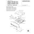
[1] Disc Loading
OPERATION DESCRIPTION
Switch ON! Disc arm(L) Disc arm(R)
(1) Turning the loading switch ON 1) When a disc is inserted, the disc arms open to the left and right and the claw below disc arm (L) sets the loading switch ON. 2) The above starts the motor rotation.
Disc
(2) Loading the disc 1) When the motor starts rotation, the worm gear also starts to turn as shown in the figure. 2) The rotation force is transmitted to the gear train. 3) When the force is transmitted to the final gear, the rollers rotate to pull in the disc.
Worm gear
Motor
Disc guide Disc IN Rubber rollers
Dis
Disc OUT Roller
The disc is pulled in or out when the rollers are pushed against the disc guide.
Side view Disc IN
[2] Operation of Slider (R)
(1) Activating the trigger arm 1) When the disc is pulled in by the rollers, the disc edge pushes the trigger arm and rotates it.
Position pushed by the disc Trigger arm
Center of rotation
2) When the disc is an 8cm disc, it is pulled upwards by the tapering on the disc guide. The trigger arm is rotated when the disc pushes the claw (section A) located before the trigger arm.
Disc Clamper chassis
When the 8cm disc reaches the loading end position, the roller areas supporting the disc decreases. To prevent the disc from dropping in this case, the claw is provided with a projection for supporting the disc.
A
Trigger arm
Claw (A) Projection 8cm Disc Disc
6
|
|
|
> |
|