|
|
|
Who's Online
There currently are 5971 guests online. |
|
Categories
|
|
Information
|
|
Featured Product
|
|
|
 |
|
|
There are currently no product reviews.
 ;
VERY GOOD SERVICE.FAST ANS VERY HONEST PRICE .RHAANK HERNAN
 ;
Thanks to this service manual I repaired my old camcorder! The manual perfectly explains how to disassemble the camcorder step by step.
 ;
This manual is very useful because it presents the technical specifications of the cd player, including the manufacturer of the reader, this helps if you need to replace it. It also displays the settings and layout of the circuit.
 ;
Manual was a good representation of service infomation for the EWV404. It worked well for my repair.
 ;
Great quality copy, right what I was looking for, all I need to fix my radio.
Thanks
XC-L7
6.2 TUNER SECTION
6.2.1 FM TUNER SECTION
� Set the mode selector to FM BAND. � Connect the wiring as shown in Fig. 1.
Step No. 1 2 Adjustment Title Front End Sensitivity TUNED IND. Lighting Level FM SG (1kHz, ± 75kHz dev.) Frequency Level (MHz) (dBµV) 98 98 0-30 18 ± 2 Reception Frequency Display 98MHz 98MHz Adjustment Location L6402 T6401 VR6201 Specifications Adjust so that the DC voltage between the IC6201pin 20 and GND becomes at maximum level. Adjust so that the indicator of TUNED IND. starts to light up.
Note: Before adjusting, make sure there is no gap between L6401 and L6402. If there is a gap between them, bring them into contact with each other first, and then make adjustments.
6.2.2 AM TUNER SECTION
� Set the mode selector to AM BAND. � Connect the wiring as shown in Fig. 1.
Step No. 1 Adjustment Title Front End Sensitivity AM SG (400Hz, 30% Mod.) Frequency Level (kHz) (dBµV/m) 999 (�1) 35-45 Reception Frequency Display 999kHz (�1) Adjustment Location T6201 Specifications Adjust so that the DC voltage between the IC6201pin 20 and GND becomes at maximum level.
Note (�1): For the area using 10kHz step, frequencies should be 1000kHz.
60cm Loop antenna
AM SG
Center
Center
AM antenna terminal
MPX SG
FM SG FM75� antenna terminal
PRODUCT
DC Voltmeter
Fig. 1 AM and FM Adjustment Wiring Diagram
FM/AM TUNER MODULE
AM antenna terminal
SIDE A
T6201
YELLOW
BLACK AXX7041 IC6201 Pin 20 T6401 L6401 VR6201
FM antenna terminal
L6402
Fig. 2 Adjustment Point
44
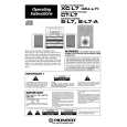
 $4.99 XCL7 PIONEER
Owner's Manual Complete owner's manual in digital format. The manual will be available for download as PDF file aft…
|
|
 |
> |
|
