|
|
|
Who's Online
There currently are 5662 guests online. |
|
Categories
|
|
Information
|
|
Featured Product
|
|
|
 |
|
|
There are currently no product reviews.
 ;
The service manual is a good quality scan of the Panasonic NV-850, which is electrically identical to the Philips VR 6920, but mecanically just nearly.
 ;
The service manual is a good quality scan of the Blaupunkt RTV-404, which is electrically and mecanically identical to the Panasonic NV-830.
 ;
completo manual bien detallado y de buena calidad de impresion , se echa en falta los esquemas de placa y parte de algun diagrama.
 ;
perfecto manual ,completo y detallado de muy buena calidad de impresion, ideal en una palabra.
 ;
un manual completo con una calidad de imagen buena con explicaciones en varios idiomas de los ajustes y detalles en conjunto un OK.
ADJUSTMENT � 2 <TUNER>
< TUNER SECTION >
1. Clock Frequency Check Settings : � Test point : TP2 (CLK) Method : Set to MW 1602kHz and check that the test point is 2052kHz ± 45Hz. 2. MW VT Check Settings : � Test point : TP1 (VT) Method : Set to MW 1602kHz and check that the test point is less than 8.0V. Then set to MW 531kHz and check that the test point is more than 0.6V. 3. MW Tracking Adjustment Settings : � Test point : TP8 (Lch), TP9 (Rch) � Adjustment location : L981 (1/3) Method : Set to MW 999kHz and adjust L981 (1/3) so that the test point becomes maximum. 4. LW VT Adjustment Settings : � Test point : TP1 (VT) � Adjustment location : L942 Method : Set to LW 144kHz and adjust L942 so that the test point becomes 1.3V ± 0.05V. Then set to LW 290kHz and check that the test point is less than 8.0V. 5. LW Tracking Adjustment Settings : � Test point : TP8 (Lch), TP9 (Rch) � Adjustment location : L941 ........................... 144kHz TC942 ......................... 290kHz Method : Set up TC942 to center before adjustment. The level at 144kHz is adjusted to MAX by L941. Then the level at 290kHz is adjusted to MAX by TC942. 6. AM IF Adjustment Settings : � Test point : TP8 (Lch), TP9 (Rch) � Adjustment location : L772 ........................... 450kHz 7. FM VT Check Settings : � Test point : TP1 (VT) Method : Set to FM 108.0MHz and check that the test point is less than 8.0V. Then set to FM 87.5MHz and check that the test point is more than 0.5V. 8. FM Tracking Check Settings : � Test point : TP8 (Lch), TP9 (Rch) Method : Set to FM 98.0MHz and check that the test point is less than 13dBµV. 9. DC Balance / Mono Distortion Adjustment Settings : � Test point : TP3,TP4 (DC balance) � Adjustment location : L771 � Input level : 60dBµV Method : Set to FM 98.0MHz and adjust L771 so that the voltage between TP3 and TP4 becomes 0V ± 0.04V. Next, check that the distortion is less than 1.3%. 10. Output Level Check <MW> Settings : � Test point : TP8 (Lch), TP9 (Rch) � Input level : 74dBµV Method : Set to MW 999kHz and check that the test point is 130mV ± 3dB. <FM> Settings : � Test point : TP8 (Lch), TP9 (Rch) � Input level : 60dBµV Method : Set to FM 98.0MHz and check that the test point is 520mV ± 3dB. 11. FM Separation Check Settings : � Test point : TP8 (Lch), TP9 (Rch) � Input level : 60dBµV Method : Set to FM 98.0MHz and check that the test point is more than 12dB.
� 48 �
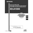
 $4.99 XHA1000 AIWA
Owner's Manual Complete owner's manual in digital format. The manual will be available for download as PDF file aft…
|
|
 |
> |
|
