|
|
|
Categories
|
|
Information
|
|
Featured Product
|
|
|
 |
|
|
There are currently no product reviews.
 ;
Exactly what was needed to assess the product - excellent value and great service
 ;
Nice to have the service manual for the Sony DCR-TRV345E now. The document is of excellent quality.
;
MACKIE HR824 26 pages English-only Service Manual contains:
1) HR824 technical overview with the description of front and rear panel switches.
2) HR824 specs
3) Block Diagram
4) Wiring Diagram
5) Packaging management
6) Spare part & final assembly list (for PCB rev A and B) + exploded view
7) Test Procedures (where, how to measure voltage...) including Test Point diagram on the PCB.
8) IC and Transistor charts.
Excellent guide: very clear, good scan quality enabling us to print readable diagram :-)
Note:
Mackie HR824 make extensive use of surface mount devices (SMD). Service on the HR824 must
only be undertaken by experienced service technicians with the right tools, experience and patience to perform surface mount rework when needed.
;
This Service manual is very well scanned and its clean to read, no any anti-theft words that un-english could understand. I got my CCD600 working with this manual and it´s clear shematics :)
;
I was very pleased with the service provided and was surprised at how good the quality was of the manual. I thought it may be a third generation copy or so, but it is as good as the websites that charge 3 times this much. I repair some electronics for family and friends without charge, so this is perfect for me. Thank you very much.
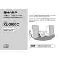
XL-3000/3000C
� Laser failure.
Is +6.2V applied to the emiter of Q861 ? No Yes Check the PWB pattern between emiter of Q607 and emiter of Q861.
Is +5V applied to the collector of Q861 ? No Yes
Check the peripheral parts of IC804 and Q861.
Is +5V applied to the pin 62 (VDD) of IC802 ? No Yes Is +5V applied to the pin 1 (VCC) of IC801 ? No Yes
Check the PWB pattern between collector of Q861 and pin 62 of IC802.
Check the PWB pattern between collector of Q861 and pin 1 of IC801.
Is 0V applied to the pin 57 (SEL) of IC802 ? No Yes
Does the laser come on when pattern cut between pin 8 (SEL) of IC801 and pin 57 (SEL) of IC802 ? Yes
No Check the PWB pattern between IC701 and IC802 (BUCK/CCE/ BUS0~3) Is approx. 2V applied to the collector of Q801. Yes Check CNP802/CNW3. If it is normal, the optical pickup is faulty. Check the peripheral parts of IC801 and Q801. If it is normal, the optical pickup is faulty.
No
� Focus failure.
Does the optical pickup move up and down when the disc is removed? Yes Is the following waveform ouput at the pin 43 (FEI) of IC802 when the disc is set? Yes
pin 43 (FEI)
No
Check as stated in item "FOCUS SERVO SAWTOOTH WAVE FAILURE".
Check the periphery of IC801 and CNP802/CNW3. Is it normal? No Yes The optical pickup is faulty.
pin 48 (FOO)
pin 44 (SBAD)
Is the waveform shown above input at the pin 44 (SBAD) of IC802? Yes IC801 is faulty.
No
Check the pattern between pin 13 of IC801 and pin 44 of IC802. Check the periphery of IC801 and CNP802/CNW3.
� 40 �
|
|
|
> |
|
|
Parse Time: 0.249 - Number of Queries: 102 - Query Time: 0.066