|
|
|
Categories
|
|
Information
|
|
Featured Product
|
|
|
 |
|
|
There are currently no product reviews.
 ;
Very quick response. Very good and accurate print quality of the scanned document.
 ;
The service manual was very usable and clear enough to see the individual values of all of the components (unlike some of the service manuals I have gotten in the past from web sites similar to this one). The price was right and the information was greatly appreciated. It helped me with an otherwise very difficult repair. It was much needed and appreciated. A faster turn around on my order would be nice, but I understand the constraints on your staff's time. Thank you for your service.
;
Excellent manual. Helped me out with disassembling and troubleshooting my projector.
;
thanks you are the best.Very good detail, Quick service response. A useful service manual with all details.
;
Great service!!! Polecam gorąco wszystkim zainteresowanym
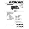
XM-1004GX SECTION 3 ELECTRICAL ADJUSTMENT
Bias Adjustment
Note : The Bias adjustment should be performed only if any of Q108 and Q110 for VR101, Q208 and Q210 for VR201, Q308 and Q310 for VR301, and Q408 and Q410 for VR401 are replaced. Setting :
Stabilized Power supply Digital Voltmeter
Adjustment Location :
� AMP BOARD (COMPONENT SIDE) � VR201 BIAS ADJUSTMENT (FRONT R-CH) VR301 BIAS ADJUSTMENT (REAR L-CH)
B+,REM terminals
set
+ _
VR101 BIAS ADJUSTMENT (FRONT L-CH)
VR401 BIAS ADJUSTMENT (REAR R-CH)
GND terminal
test points
Test Point Location : Procedure: 1. Rotate variable resistors VR101 (FRONT L-CH), VR201 (FRONT R-CH), VR301 (REAR L-CH) and VR401 (REAR RCH) full counterclockwise as seen from the pattern side to minimize the bias current. 2. The input signal is with no signal. 3. Connect the stabilized power supply between B+ and REM terminals and gradually increase the voltage to 14.4 V while checking for any abnormal current. 4. Adjust VR101 (FRONT L-CH), VR201 (FRONT R-CH), VR301 (REAR L-CH) and VR401 (REAR R-CH) so that the digital voltmeter connected between the respective test points reads 4.5±1 mV. RV Ref. No. VR101 VR201 VR301 VR401 Test points TP101 and TP102 TP201 and TP202 TP301 and TP302 TP401 and TP402
� AMP BOARD (CONDUCTOR SIDE) �
TP302 TP301
TP201 TP202
TP402 TP401
TP101 TP102
8
|
|
|
> |
|
|
Parse Time: 0.322 - Number of Queries: 103 - Query Time: 0.072