|
|
|
Who's Online
There currently are 5812 guests online. |
|
Categories
|
|
Information
|
|
Featured Product
|
|
|
 |
|
|
There are currently no product reviews.
 ;
Very good documentation for the Grundig 2077 model (as well as similar 800/900/1000 series radios). The first two pages are a summary of reception specifications and output capability. The third page is the tuner dial indicator and dial cord routing diagram. the final ~5 pages are the schematics for the various models (including 2077). The scan quality of the schematics are good, adn can be easily read if zoomed in. The documents are in German, not English as stated. It would have been nice to have the tuning sequence and settings, and some trouble shooting materials... or component and wiring map.
 ;
Perfect like it was descriped, Perfect like it was descriped
 ;
Very good detail, all pages clear, exactly what I needed
 ;
Excellent service, and just what I needed to service my TU-7700. All pages of the manual are clear and easily readable.
 ;
Excellent printing quality.
A complete and very usefull service manual with all details.
GREAT SERVICE AT VERY LOW PRICE!
A+++++++++++++++++++++++++
ADJUSTMENT <TUNER / DECK>
< TUNER SECTION >
1. Clock Frequency Check Settings : � Test point : TP2 (CLK) Method : Set to AM 1710 kHz and check that the test point is 2160 kHz ± 45 Hz. 2. AM VT Check Settings : � Test point : TP1 (VT) Method : Set to AM 1710 kHz and check that the test point is less than 8.5 V. Then set to AM 530 kHz and check that the test point is more than 0.6 V. 3. AM Tracking Adjustment Settings : � Test point : TP8 (Rch), TP9 (Lch) � Adjustment location : L951(1/3) Method : Set to AM 1000 kHz and adjust L951(1/3) so that the test point becomes maximum. 4. AM IF Adjustment Settings : � Test point : TP8 (Rch), TP9 (Lch) � Adjustment location : L802 L802 ................................................... 450 kHz 5. FM VT Adjustment Settings : � Test point : TP1 (VT) � Adjustment location : L907 Method : Set to FM 108.0 MHz and adjust the L907 so that the test point is 7.00 V ± 0.05 V. 6. FM VT Check Settings : � Test point : TP1 (VT) Method : Set to FM 87.5 MHz check that the test point is more than 0.5 V. 7. FM Tracking Adjustment Settings : � Test point : TP8 (Rch), TP9 (Lch) � Adjustment location: L904 Method : Set to FM 98.0 MHz and adjust L904 so that the test point becomes maximum and distortion to minmum. 8. FM Tracking Check Settings : � Test point : TP8 (Rch), TP9 (Lch) Method : Set to FM 98.0 MHz and check that the test point is less than 9 dBµV. 9. DC Balance / Mono Distortion Adjustment Settings : � Test point : TP3, TP4 (DC Balance) TP8 (LCH), TP9 (RCH) (Mono Distortion) � Adjustment location : L801 � Input level : 60 dBµV Method : Set to FM 98.0 MHz and adjust L801 so that the voltage between TP3 and TP4 becomes 0 V ± 500 mV with minimum distortion. 10. Output Level Check <AM> Settings : � Test point : TP8 (Rch), TP9 (Lch) � Input level : 74 dBµV Method : Set to AM1000 kHz and check that the test point is 55 mV ± 3 dB. <FM> Settings : � Test point : TP8 (Rch), TP9 (Lch) � Input level : 60 dBµV Method : Set to FM 98.0MHz and check that the test point is 270 mV ± 3 dB. 11. FM Separation Check Settings : � Test point : TP8 (Rch), TP9 (Lch) � Input level : 60 dBµV Method : Set to FM 98.0 MHz and check that the separation more than 25 dB.
< DECK SECTION >
1. Tape Speed Check Settings : � Test tape : Method : TTA�100
� Test point : SP OUT Play back the test tape and check the test point is 3000 Hz ± 5 Hz (FWD) and FWD speed ± 45 Hz (REV).
2. Head Azimuth Adjustment Settings : � Test tape : TTA�330 � Test point : SP OUT � Adjustment location : Head azimuth adjustment screw Method : Play back (FWD) the 8 kHz signal of the test tape and adjust screw so that the output becomes maximum. Next, perform on REV PLAY mode. 3. PB Frequency Response Check Settings : � Test tape : TTA�320 � Test point : SP OUT Method : Play back the 315 Hz and 10 kHz signals of the test tape and check that the output ratio of the 10 kHz signal with respect to that of the 315 Hz signal is -3 dB ± 3 dB. 4. REC/PB Frequency Response Check Settings : � Test tape : TTA�602 � Test point : SP OUT � Input signal : 8 kHz/1 kHz (-20 VU / 0dB) Method : Apply a 1 kHz signal and REC mode. Record and play back the 1 kHz signals and check that the output is -2 dB ± 3 dB.
� 31 �
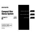
 $4.99 XRM171 AIWA
Owner's Manual Complete owner's manual in digital format. The manual will be available for download as PDF file aft…
|
|
 |
> |
|
