|
|
|
Categories
|
|
Information
|
|
Featured Product
|
|
|
 |
|
|
There are currently no product reviews.
 ;
I was having a hard time finding the problem with this Mackie 1604 unit. I didn't have a schematic. Went looking on the web and found your site and the price was more then reasonable. Ordered it and within the hour had the manual and within 15 minutes had the unit fixed. Best $4.99 I ever spent. Thank you.
Doug
;
This is a service manual in every sense of the word ( French and German versions of the text are included, as well as English..)
There are explanations of the mechanical and electrical functions, plenty of mechanical drawings, and the needed schematics. The quality of the scanning is excellent - all the component values are clearly legible - and very usefully there are pcb component layouts, so you can find a component on the schematic, and then very quicky pinpoint its physical location on the relevant pcb.
I cannot see how I can give this manual any less than the maximum 5 stars! Great value for money, which will pay for itself immediately. Excellent all round!
;
the manual is great and especially hard to find... thanks for the great service and having a hard to find manuel_
;
Please tell us what you think and share your opinions with others. Be sure to focus your comments on the product. You will receive $2.50 of store credit for Your review.
;
hat alles sehr gut geklappt. Das Servicemaual ist gut zu verwenden. Die Pläne und Schrift
ist klar und leserlich. Außerdem preiswert. Grüße an alle Hifi-Bastler
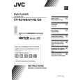
3.1.3 Removing the mechanism assembly (See Figure 2, Figure 5, Figure 6) � Prior to performing the following procedure, remove the top CN202 cover. C C CN101 � There is no need to remove the front panel assembly. (1) Insert a kind of screwdriver in a hole located in the right side of mechanism assembly, and push a lever until it cannot be inserted any further. (2) And then, a tray will come out. Remove the tray in an upper direction, with slightly opening the lower part of fitting in an outward direction. (3) Remove the three screws C attaching the mechanism assembly. (4) A tray is made to slide ahead. (5) A gear 1 is turned counterclockwise. Then, a pick-up unit Mechanism assembly C Main board moves back. CN201 (6) It solders to two c sections on the pick-up unit. Fig.5 (7) Disconnect the card wire from connector CN201, CN202, CN101 on the main board. ATTENTION: Please extract the wire after short-circuited of two places on the wire in part c with solder. Please remove the solder two places of part c after connecting the wire with CN101 when reassembling. CAUTION: Be sure to solder the short land sections �c� on the pickup unit before disconnecting the card wire from connector CN101 on the main board. If the card wire is disconnected without attaching solder, the pick-up unit may be destroyed by static electricity. (8) Remove the mechanism assembly by lifting the rear part of the mechanism assembly.
Gear1
Part c Pick-up Fig.6
(No.XA016)1-9
 $4.99 XV-N212S JVC
Owner's Manual Complete owner's manual in digital format. The manual will be available for download as PDF file aft…
|
|
|
> |
|