|
|
|
Who's Online
There currently are 5973 guests online. |
|
Categories
|
|
Information
|
|
Featured Product
|
|
|
 |
|
|
There are currently no product reviews.
 ;
Good quality, all schematics of few of models. There is also short form of user manual and regulation manual.
 ;
Perfect copy of the service manual. you can enlarge every page, and it comes up
with all details.
 ;
It´s very very nice manual with all, what i need. Original in good quality. Very fast business. Very much thanks...
 ;
Purchased the manual that I was looking for at a great price and could download it easily.. Great service experience and for future purchases I plan to use the site.
Thank you very much
 ;
Exactly what was needed to assess the product - excellent value and great service
IC DESCRIPTION
IC, pPD780228-xxx-xxx Pin No. 1 Pin Name K-SCAN I REVOLA RE VOL B D-CD D-AUX
& 1
1/0 o I
,
Description Key scan output. PALS data input A for encoder volume. PALS data input B for encoder volume. CD function LED control. AUX function LED control. Tuner function LED control. Tape funtion LED control. Line Mute control for PRO-logic unit. CD unit power ON control. (H:ON) Tuner block power ON control. (H:ON) Bias oscillator control. (H:oscillation) REC MUTE control. (LREC) I TAPE 1/2 select control. (H:DECK1 play) POWER ON control for audio block. (LPower ON) Latch control for shift register. CD flash window control. (H:Light up) Extension port (connected to GND).
Pin No. 43 44 45 46 47 48 49
Pin Name I-CD-SW I-DISH I-RE-JOG I-SIG I-SPEANA I-KEY2 I-KEY1
I
1/0 I I I I I I I CD tray SW detector. CD turn-table detector. Pulse data input for rotary encoder. Tuner RDS signal level input. Data input for SPEANA light up. Tact key level input 2. Tact key level input 1. I GND input for AD transfer. FL segment scan output.
Description
I
2 3
4
I
I
I
II Io I o o
,
I
I
5 6 7
I
r
D-TUNER D-TAPE O-MUTE O-CD ON O-TU ON O-BIAS O-RMT O-CD LED O-PB1 O-POWER O-FCE
I
8 9 10 11 12 13 14 16
I
Io Io
I
50
AVSS P1-P8 P9/TM-BAsE PIO/RDS P1l/OIRT P15/PRO P16/DSP P17 P12/LW
I
o 1/0 1/0
I
I
Io
Io
51-58 59 60
I
,
I
FL segment scan output/TM base input. FL segment scan output/ RDS mode detect. FL segment scan output/ OIRT mode detect. FL segment scan output/ LW mode detect. FL segment scan output/PRO-Logic mode detect.
10
I
o
o
I
61 62 65 64 63.
1/0
1/0 1/0 1/0 1/0
I
15
I
17 18
I
Ic
Vss
1- 1 I- I 1IO 10
1
IO
o
k=
66
P13/AM.sT+FM.w P14/AM9K
FL segment scan output/AM stereo+ FM wide mode detect. FL segment scan output/Initial AM 9K mode detect.
1/0 1/0 I
FL segment scan output/DSP mode detect. FL segment scan output.
System GND. System VDD supply. CD turn table REVRSE control. (H:Reverse) CD turn table FORWARD control. (H:Forward) CD tray OPEN data output. (LOpen)
+
67
I
19
20
I
I
VDD O-DISH RVS O-DISH FWD O-OPEN
1
I I
1
I
68 69 70 71 72-78 79
80
I
P18/HP MUTE SPEANA AfP19 SPEANA B/P 20 SPEANA C/P 21 P22�P28 VDD2
-VFL
1/0 1/0 1/0 1/0
FL segment scan output/ Head Phone Mute input. FL segment scan output/ SPEANA level input timing A. FL segment scan output/ SPEANA level input timing B. FL segment scan output/ SPEANA level input timing C. FL segment scan output. System VDD supply. Power supply for FLdisplay. FL segment scan output/TAPE REC SW detect. FL segment scan output/TAPE PLAY1 SW detect. FL segment scan output/TAPE PLAY2 SW detect. FL segment scan output. FL grid scan output. � I I
I
t
21 22 23 24
25
I
1
o
O I I I
1
I I
I
O-CLOSE I I-SQ.DATA/i= I
1
CD tray CLOSE data output. (LClose) CD SUBQ data input/tuner IF count input.
CD SUBQ clock ouput / tuner mono,stereo selection input. (LStereo)
oI
I
I 1/0 I 1/0 I 1/0 I
10-SQ.CLKHI13RE0 I CLOCK/DSC
I
vo
I 1/0 I O I
26 27 28 29 30 I 31 32 33 34 35
IO
Clock output for shift register, DSP & PRO unit / DSC control for PRO unit CD sense input/Tuner PLL chip enable output. CD data output/Tuner PLL clock output.
81
P29/REC I I I P30/PBl P31/PB2 P32-P35 G13NG1
I I-SENS/O-PLLCE
I
IO-CDDATA/PLLCLKl
I I
I
82 83 84-87
I O-XLT/I-RDS CLK I I/O
I
I
CD XLT output /Tuner RDS clock input. Micon reset input. CDclockoutput/Tuner RDS data input.
o
o
I
Ei5s
111
1/0
I
88-1oo I
10-CLw-RDSDATAl PRO-CE DATA/FDSC I-RMC O-PLL DATA
I
1
o o
I o
1
Latch control for PRO-Logic IC and DSP IC. Data control for shift register, DSP & Pro unit/ DSC control for IC,M62439SP. Serial data input from remote controller. DSC control for Function IC / Tuner PLL data output. Micon clock shift output. Clock circuit VDD.
4.91MHz oscillator circuit.
36 37 38 39 40 41 42
O-C.SHIFI� VDD1
x2
o
xl Vssl AVDD HOLD I I
4.91 MHz oscillator circuit. Clock circuit VDD. VDD input for AD transfer. AC/ DC detector.
-39�
-40-
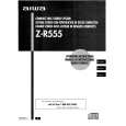
 $4.99 ZR555 AIWA
Owner's Manual Complete owner's manual in digital format. The manual will be available for download as PDF file aft…
|
|
 |
> |
|
